Author Archives: Derick

Vertical mezzanine gate in the down position

The Newly Redesigned Vertical Lifting Mezzanine Gate

Vertical mezzanine gate in raised position

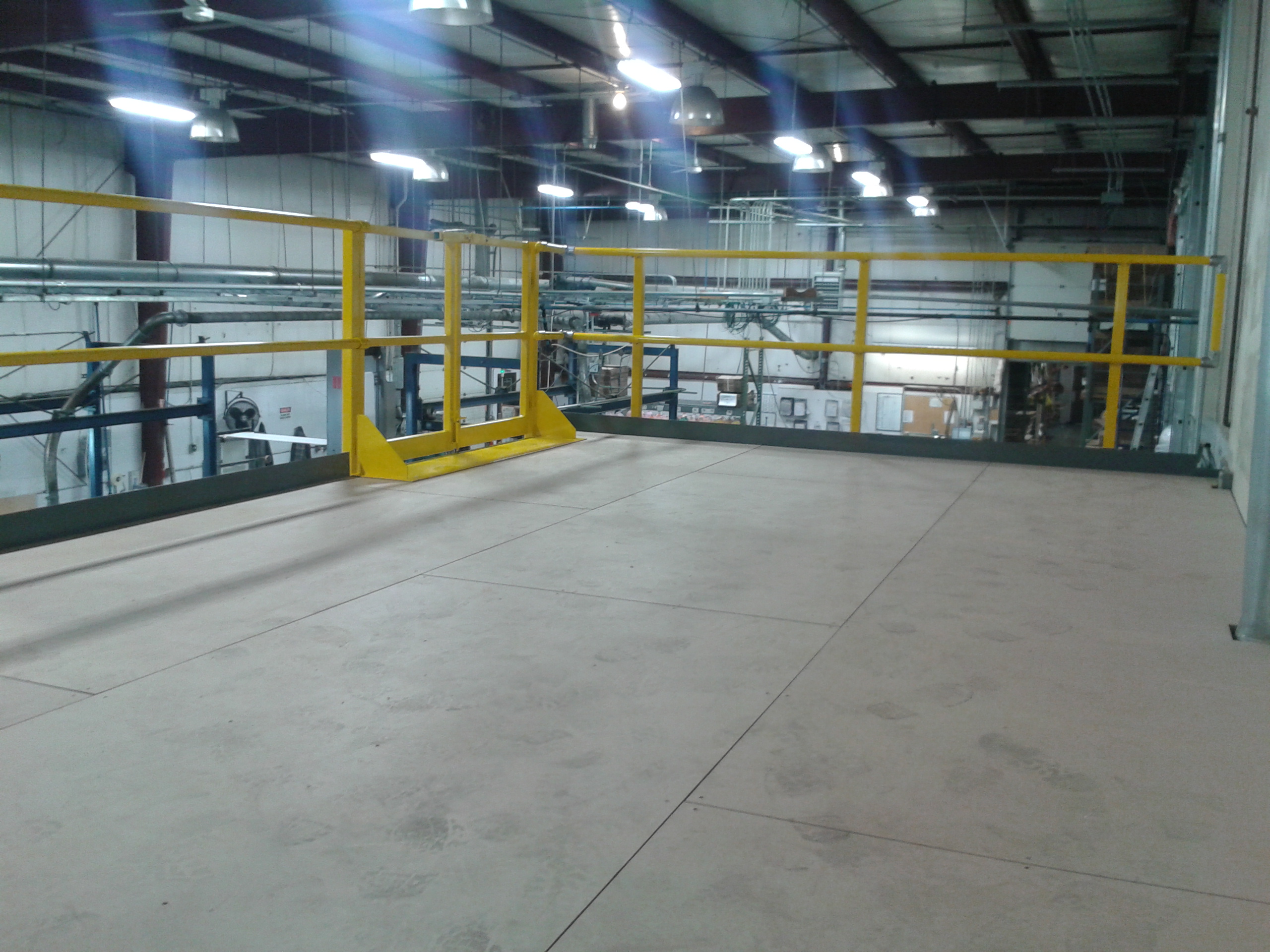
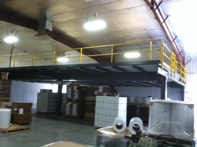
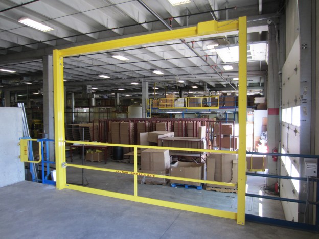
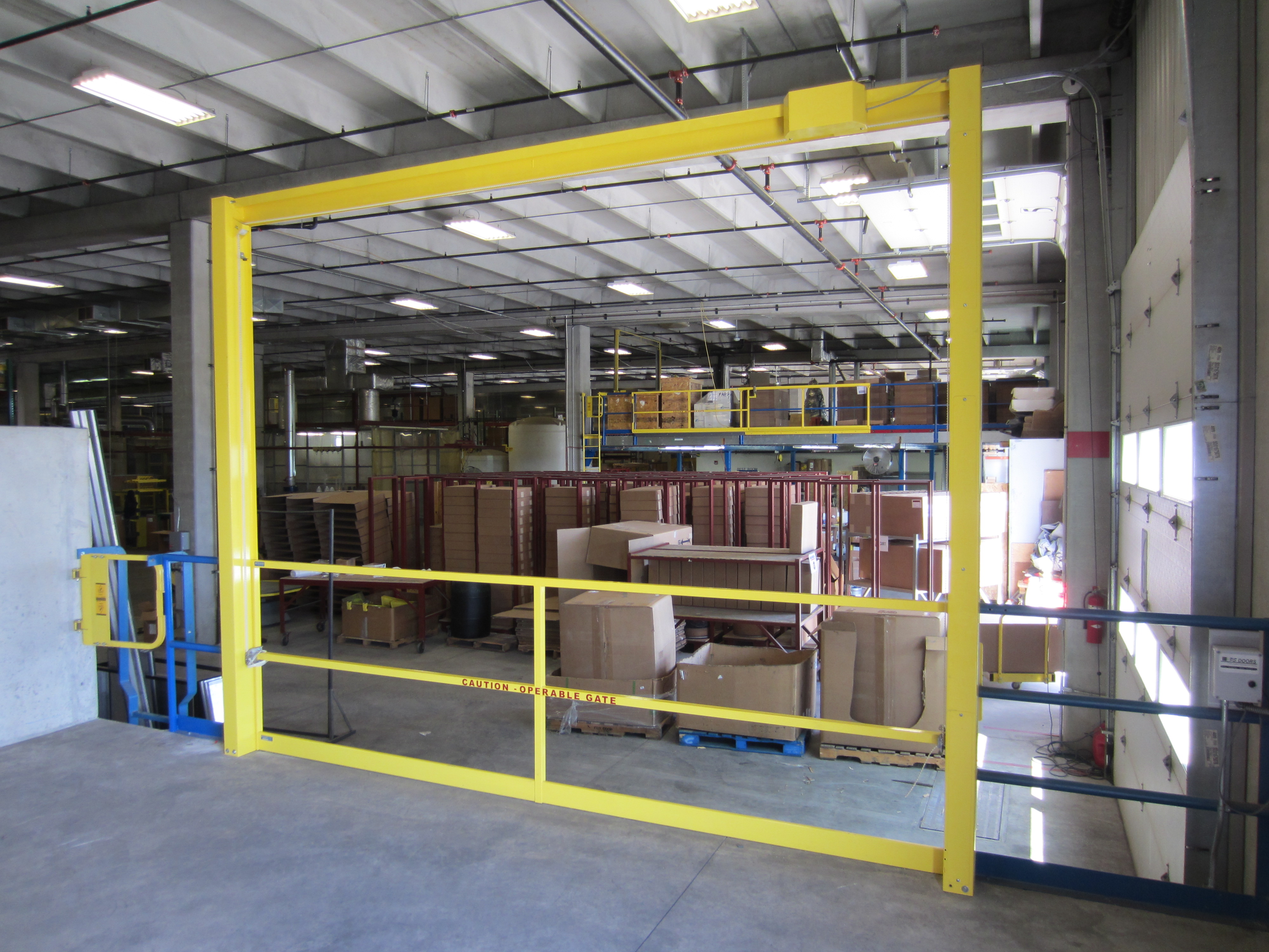
Electric vertical lifting mezzanine gate in action

By Derick @ A-Mezz

Recently, the vertical lifting mezzanine gate received a redesign.  I’d like to take a moment to go over some of the modifications made to better assist our customers.

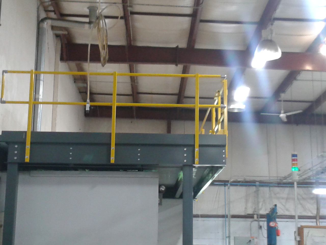
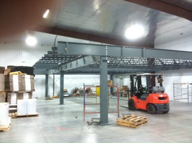
The most noticable change in the design was to how the gate moves along the columns.  In the old design the gate traveled to approximately 6” from the top of the column.  This would vary a bit depending on the size of the counterweight required.  We most commonly used a 12’ tall column which would allow for approximately an 8’ clearance height under the raised gate.   The gates operation has changed slightly.  We now typically use a 10’ tall column and the gate now travels beyond the columns by 6” allowing for a 7’ clear height under the raised gate.  As before, custom heights are still available, but by more efficiently utilizing our customers’ vertical space, the new vertical mezzanine gate is a great option in more locations.

Vertical mezzanine gate in the down position

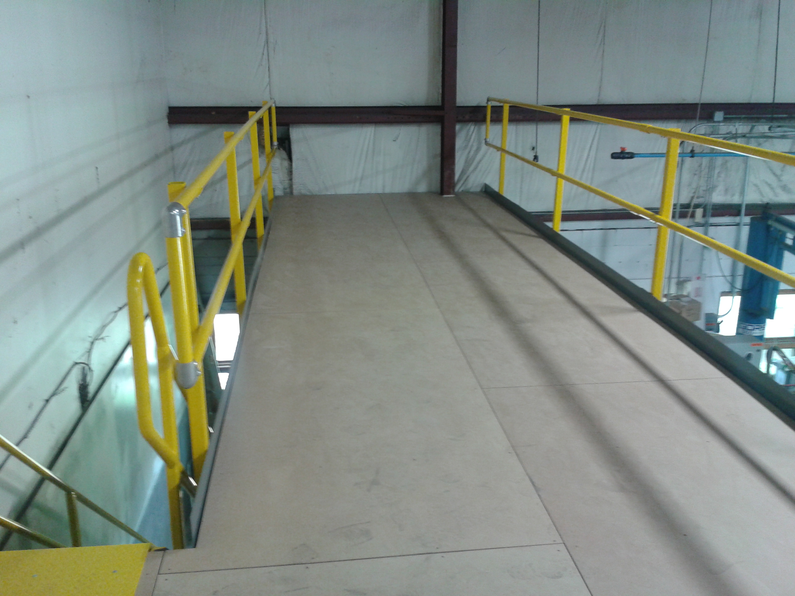
Closed electric vertical lifting mezzanine gate

One of primary goals for the redesign was to improve the lead time.  In the old design, every mezzanine gate was a custom unit.  Each mezzanine gate would require its own set of drawings to be drafted, and would need to be made from scratch as the orders where approved.  In the redesigned gate, many of the components where standardized.  We are now able to provide our vertical mezzanine gate customers with their approval drawings typically in a day or two, and improved the overall production cycle as well to about 6 weeks on average.  To further improve our lead times, we took two of our most requested sizes and began stocking many of the components.  We can now typically ship out standard 6’ or 8’ clear width vertical mezzanine gates in powder coated mild steel in about 3 weeks on average.

Our vertical mezzanine gates have always been available in manual, electric, pneumatic with electric controls, or fully pneumatic for explosive environments.  From time to time we receive calls from customers who previously purchased a manual mezzanine gate and wanting to upgrade it to an automated unit.  Unfortunately with the old design there was no easy way to convert it, and the customers would need to replace the gate.  With the redesigned vertical mezzanine gate, a customer can purchase a manual gate, and in the future if they are looking to upgrade it purchase a kit to easily convert their existing gate in the field.  When the factory built their prototype, it only took them 15 minutes to convert a manual vertical mezzanine gate into an electric gate.

We’re really pleased with how the redesigned vertical mezzanine gate turned out.  The changes in the design have made a marked improvement in the lead times while not just maintaining its adaptability, but improving it.


Relocating a Modular Office

A-Wall 200 modular in-plant office.  Still in great shape after one reconfiguration and 6+ years of use.

A-Wall 200 modular in-plant office. Still in great shape after one reconfiguration and 6+ years of use.

One of the major advantages of modular building systems over traditional construction is their ability to adapt to your changing needs.  Let’s take this project for example.

6+ year old A-Wall 200 modular office.  Here, the first reconfiguration moved the door from the other side of the building.

6+ year old modular office after the first reconfiguration moving the door from the other side of the building.

Back in early 2008, we provided the customer with a 24’ wide x 42’ long x 9’ high modular in-plant office.  The original layout had three doors. There were two on one 24’ end, and one on the other.  A few years later as their layout around the building was changing, the 24’ long wall with two doors was going to get blocked off.   By disassembling a portion of the building and swapping 4’ panels with one another, the customer was able to relocate the doors to the 42’ long walls.

Over the years the customer’s needs continued to change.   They recently decided to remove the in-plant office.   If this was built out of traditional construction, the office space would be torn down and that would be the

Installing the reconfigured in-plant office in its new location. Recessed beams used to support the roof deck due to the long spans.

Installing the reconfigured in-plant office in its new location. Recessed beams used to support the roof deck due to the long spans.

end of it.  However, as this was modular construction, the customer found another spot in their plant where the building could be relocated in a slightly smaller (24’ wide x 34’ long) form.

We were able to reuse almost all of the materials when we relocated it.  We replaced the base track, as well as the ceiling grid and tiles.  The base track is very difficult to remove without creating kinks in the channel.   As the panels fit very snuggly into new base track, any kink in the track can make it almost impossible to fit.  Likewise, the material cost to replace the ceiling grid and tiles is usually significantly less than the additional labor to carefully disassemble the ceiling for reuse.

Relocating the modular office panels

Relocating the modular office panels

There were some additional considerations that went into the reconfiguration to maximize the materials we could reuse.  On the A-Wall building systems with a non-load bearing roof, we can span the roof deck a maximum 20’.  In the original 24’x42’ layout, we used a couple of 24’ long recessed beams to break the spans approximately into thirds.  By maintaining the 24’ width and by making sure that none of the spans between beams grew, we were able to reuse the beams and roof deck without needing to order any additional material.

The modular wall system’s ability to be rearranged and reconfigured for a new application, or disassembled and re-installed in a new location, is one of this customer’s favorite features.  They’ve purchased a number of modular buildings from us over the years and most of them have been rearranged or relocated at least once.

Overview of the prefabricated mezzanine installation

By Derick

Front topside view of the completed parts storage mezzanine

Front topside view of the completed parts storage mezzanine

We’re often asked by customers if they’re able to install their mezzanine order on their own. The following series of pictures were sent to us from a customer who did just that, and should provide you with a general idea of what a mezzanine installation entails.

First, a little bit about the mezzanine. The customer was a metal welding and fabrication shop in Iowa and they were looking to move their parts storage up above the production floor. They wanted to provide their own staircase, but contacted us to design and provide them with a 46’ x 24’ mezzanine. Because this was going above their production area, they wanted to maintain at least a 10’ clearance height and to minimize the number of columns below the mezzanine deck. The mezzanine clear spanned the 24’ and broke the 46’ span into two 23’ nominal bays using a beam and c-section framing system. This left the customer plenty of space to maneuver around and work below. The deck was designed to accommodate both the point loads from their single rows of shelving as well as 125 psf distributed live load to accommodate 4’x4’ pallets up to 2000 pounds each.   With the mezzanine situated in the corner of their building, we provided industrial use two rail handrail with a 4” kick plate on the two exposed sides, as well as along the opening for the customer’s staircase per IBC code. The decking on the other two sides was extended beyond the framing to the existing walls in order to utilize deck space and eliminate the need for additional handrails. The customer added additional resindek to their girders in order to further close off the walls and protect their insulation.

Attaching the primary framing members to the columns

Attaching the primary framing members to the columns

Now for the installation of a prefabricated mezzanine, we would recommend a three man crew. You will want a fork lift on hand, and a scissor lift if possible. As everything is typically bolted together or fastened with a self-tapping screw, there is very little in the way of specialized equipment required.

Starting in the back corner and working forward, you’ll begin by positioning your columns and bolting in the primary framing members. Use the forklift to position the beams and hold them in place while you connect them as the beams can be quite heavy. A spud bar will come in handy to align your bolt holes. You will need to reach inside the square tube columns to tighten the bolts.

Connecting the secondary framing members

Connecting the secondary framing members

After the primary framing members have all been attached, your next task is to bolt the secondary framing members to the primary framing members. After all the framing is connected and tightened down, it’s time to anchor the columns to your floor with the provided concrete wedge anchors.


Installing the corrugated roof deck on the mezzanine

Installing the corrugated roof deck on the mezzanine

Next you will install the kick plate and decking to your platform. In this example we used a corrugated roof deck for the structural component and covered it with resindek. This was done to provide the customer with a cost effective and smooth surface to work on. The kick plate is an angle that goes between the roof deck and your primary framing members. This closes off the platform so you cannot see down the corrugation of the roof deck from the sides. It also protects workers below the structure from material/tools, etc. that could roll or be kicked off the top level. The roof deck sub floor is fastened down to the framing members below using the provided self-tapping screws at every valley. You’ll then need to install the deck surface and secure it to the sub floor. The tek screws for the resindek are provided in a ribbon for use with a stand-up screw gun in order to speed up the installation process, as each 4’x8’ sheet of resindek takes 20 screws to properly fasten.

Installed unfinished resindek on the completed parts storage mezzanine

Installed unfinished resindek on the completed parts storage mezzanine

We’re almost finished now. Our railing is typically mounted on the face of the mezzanine with a post that will need to be bolted on every eight feet at maximum. The railing typically ships in 21’ long pipes that are cut in the field to the appropriate lengths. The cut handrails are then connected together with the provided splices and pipe elbows, and are fastened to the saddle brackets of the posts. You will need to install the splice clips for the kick plate at every seam to establish a continuous appearance.

Underside of beam and c-section mezzanine with surface mounted lighting attached to the roof deck

Underside of beam and c-section mezzanine with surface mounted lighting attached to the roof deck

Generally you would still need to bolt the treads to the stringers and finish off the handrail for the staircase, but in this case the customer was going to fabricate their own stair.

While this has been just a general overview, your mezzanine would ship with a very detailed set of assembly drawings and instructions that would go into much greater detail on the installation. This customer was pleased with the ease everything went together and the quality of the platform.

Adding a Platform Above an Existing Walled Off Space

View from the side of the platform showing the cantilevered edge to carry the platform over the existing wall

View from the side of the platform showing the cantilevered edge to carry the platform over the existing wall

By Derick

We were contacted by a customer who had an existing walled off area on their floor that they were using for long-term storage.  They were running out of room and asked us to build a platform above it, as well as to span over another adjacent room to expand their storage space.

Overall, the platform was to be 42’ wide x 12’ deep in order to stretch over both rooms.  We needed to maintain a 10’ clearance height under the platform to clear their existing walls, and the deck was designed for light storage at 125 lbs per square foot live load, which would accommodate their light shelving storage as well potential future pallet storage for pallets up to 4’x4’ and weighing up to 2000 lbs.

View from underneath the platform with the columns and OSHA stairs dropping into an existing walled off area

View from underneath the platform with the columns and OSHA stairs dropping into an existing walled off area

We had to be very careful with the positioning of our columns on this project because the customer didn’t want anything in front of the building that might interfere with their aisle way. We set the mezzanine columns back inside the existing room and extended our deck to the front of the building.  Likewise, because the customer wanted to keep the stairs inside the footprint of the platform, the customer requested that we use an OSHA staircase as opposed to an IBC staircase. An IBC stair has a more gradual angle of decent with a 7” maximum rise for every 11” tread and requires an 11” handrail extension at the bottom (or in some locations, such as here in Ohio, 23”) An OSHA staircase with generally has around an 8” rise and 9” treads and does not require handrail extensions at the top and bottom.  The IBC staircase would not leave them with sufficient room at the bottom between the handrail extensions and the columns to access the stairs, so the decision to go with OSHA freed up some space for them.

Top of deck view of the platform with unfinished Resindek field cut around customer’s existing ductwork and a 6’ bi-parting swing gate

Top of deck view of the platform with unfinished Resindek field cut around customer’s existing ductwork and a 6’ bi-parting swing gate

For the decking we used a corrugated roof deck (painted reflective white) and skinned it with an unfinished ¾” Resindek LD.  This gave the customer a nice smooth deck surface up top and was significantly less expensive than a metal deck. The framing was held off the main walls of the building by about 6”in order to clear the base plates centered under the columns, to clear some small ducts and an existing building column the customer had running up their building’s primary walls, as well providing the installers with enough room to bolt the framing together. The decking was then run beyond the framing back to the customer’s walls and trimmed in the field by the installers to go around the customer’s existing building column and ductwork.

Top of deck view showing internal OSHA staircase and unfinished Resindek field cut around customer’s existing building column

Top of deck view showing internal OSHA staircase and unfinished Resindek field cut around customer’s existing building column

The materials were shipped out on a tarped dedicated flatbed, and were delivered the next day.  The customer unloaded the materials and staged them indoors near the work area.  They cleared out the room that we would be building in, and with no existing roof in the room that would otherwise need to be removed, they were all set for our installers.  Installation began on a Monday morning, and everything was wrapped up with another happy customer by lunch on Thursday.

Using Modular Building Materials to Consolidate the Engineering Department out onto the Shop Floor

Exterior view of the completed 140’ long  modular office complex

Exterior view of the completed 140’ long modular office complex

By Derick @ A-Mezz

Most commonly, when someone contacts us looking for a modular building system, they’re looking to put in something small — a 12’ x 12’ office, or a 16’ x 24’ conference room, for example. That is not always the case, though. Modular wall systems are rather versatile and can be used for much larger projects as well. These photos are all of one such project we put together for a happy customer here in Cleveland, Ohio.

Interior view down the hallway of offices as the project is being installed

Interior view down the hallway of offices as the project is being installed

The customer wanted to move their engineering department down onto the plant floor. Working alongside the customer, we came up with a design for a 140’ x 35’6” building system to go on the plant floor partially underneath a decommissioned bridge crane.   At one end we had eight 12’ x 12’ offices, and a 12’ x 14’ three walled “war room”.

Interior view of the 62’ span open area along with one of the existing bridge crane columns before it was enclosed

Interior view of the 62’ span open area along with one of the existing bridge crane columns before it was enclosed

The central section of the building was kept largely open to be set up for desk spaces. Typically, a corrugated roof deck is used to form a membrane that helps support the wall system. With the 62’ x 35’6” clear span across the room, we decided to support the wall panels and grid ceiling with a 4’ on center joist system that tied everything back to the support structure of the former bridge crane. The bridge crane columns were also boxed in with traditional construction to give the room a clean, finished appearance.


Finished and furnished 30’x18’ conference room.

Finished and furnished 30’x18’ conference room.

On the far end of the building we made a 30’ x 18’ conference room. The rest of the area was left connected to the main central region to be used for printers and supplies.

Primary entrance to the finished office complex .

Primary entrance to the finished office complex .

Heading into the project, one of the customer’s main concerns was to isolate their engineers from the noise of the production floor. The panels of the A-Wall 200 wall system we used offer an STC rating of 32. The internal tongue and groove connection between panels offers a uniform barrier of protection throughout the system. The areas where sound has an easier time of getting through on a wall system are usually the doors and windows. In order to help prevent this we put heavy-duty EPDM gaskets and mechanical sweeps on all the exterior doors, and used laminated glass for all the exterior windows. To further help isolate the building from the sounds of production around it, we placed a foam tape underneath the base track of the wall system, and added rolls of insulation above the acoustical grid ceiling.   After everything was put together, we had another happy customer with a quiet engineering department located right in the center of their production floor.

Cantilevered Storage Mezzanine with Wide Column Locations

mezzanine cantilevered edge

Wide span storage mezzanine with a cantilevered edge for a plastics company

By Derick @ A-Mezz

These are some photos of a mezzanine floor job we did for a site in Idaho. The contractor was looking to add a 50’ wide x 35’ deep mezzanine for additional pallet storage space in their client’s warehouse.

The warehouse’s cement pad was not initially setup to accommodate the loads from the mezzanine columns. The initial mezzanine design utilized beam and c-section framing with 12’6”x17’6” nominal column spans. While the warehouse had some existing reinforced concrete piers, they would have needed to install twelve additional footers in their pad to support the other columns. They provided us with a layout of their existing concrete piers, and asked us to come up with an option to help them limit the number of additional footers they would need to install as much as possible.

Beam and bar joist framing with extended arms on the joist allow for a cantilevered edge

Beam and bar joist framing with extended arms on the joist allow for a cantilevered edge

Utilizing a beam and bar joist frame, we were able spread our column spans out to 25’ x 28’6” nominal with a 6’6” cantilevered edge. This allowed us to set four of the six columns on top of the customer’s existing reinforced concrete piers. This also had the additional benefit of allowing for a more open space below the deck.

The customer had a couple options on how we could work around the large tapered building columns along the back wall. We could have dropped an additional column and used additional beams to frame around the center tapered building column, but the customer instead chose to pull the platform away from the wall just enough to clear them, and add some additional handrail along the back end of the cantilevered storage mezzanine for fall protection.

Unfinished resindek surface with both face and deck mounted handrail

Unfinished resindek surface with both face and deck mounted handrail

The platform was designed for a 125 pound per square foot uniform live load and used a cost effective corrugated roof deck and unfinished resindek to form the mezzanine deck.   This gave the end user a smooth surface to work on that wouldn’t peel with the rolling loads of the pallet jacks, and allowed them to store their pallets of packing materials on top of the deck as long as no pallet and pallet jack weighed over 2000 lbs.